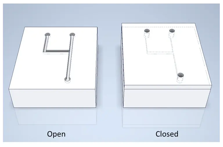
Injection molding, a mainstay for the manufacture and fabrication of thermoplastic parts, has proven itself useful in the production of plastic microarray and microfluidic devices. The advent of microinjection molding, which offers exquisite temperature control and precision microfabricated mold inserts, has brought numerous disposable plastic microdevices to market, such as the Simoa™ Disc (Quanterix), DropPlate (Unchained Labs), and MALDI-MS (Biomérieux / Shimadzu Biotech).
In injection molding, thermoplastic is injected in molten form into a closed cavity, allowing for higher throughput and superior durability compared to the traditional material of microfluidics, polymethylsiloxane (PDMS.) The downsides of this process include high mold costs, long tool fabrication time, and significant geometric limitations on possible microfeatures.
An alternative form of manufacturing, embossing, offers numerous advantages. In embossing, plastic starts in solid form inside an open cavity and is thermoformed by a combination of heat and pressure as the cavity closes. Microfluidic devices fabricated by embossing have improved replication accuracy, less shrinkage and warpage, and lower overall cost compared to devices made using injection molding [1,2].

Figure 1: Comparison of injection molding and embossing processes.
Embossing with soft tools
Embossing itself can take several different forms. The most widely-used version, known as “hot embossing” or “hard embossing”, involves pushing a heated mold into a plastic block or sheet, imprinting features onto the plastic surface.
Edge Embossing uses a form of embossing called “soft embossing”, where mold surfaces are made from a high-durometer elastomeric material that faithfully reproduces features ranging in size from macroscale through-holes and reservoirs to microscale channels, wells, and even sub-micron features. Unlike hard embossing, the entire shot of plastic reaches a uniform melting temperature, allowing thermoforming of both large features and exquisite microscale features. The elastomeric nature of the tool’s surface allows for the molding of delicate microfeatures with high aspect ratios and little to no draft angle, as well as a gentle ejection process that prevents damage to the part or the tool.
Fabricating microfluidic devices by soft embossing
To illustrate how the embossing process is implemented, consider the steps involved in fabricating a microfluidic device designed to generate picoliter-sized droplets. A simplified schematic of a droplet-generating device is shown in Figure 2. The device functions by introducing two immiscible fluids at a T-junction. By varying the flow rates, fluid properties, and channel dimensions, monodispersed droplets of tunable sizes can be produced at kHz rates[3].

Figure 2 – Droplet generating device featuring two inlets that meet at an interface producing regular microscale droplets. As the dispersed phase fluid (supplied by inlet 1) enters the primary channel containing the continuous phase (supplied by inlet 2) the dispersed phase is exposed to shear forces that elongate the portion of the fluid extending into the primary channel, eventually forming a neck and breaking off into monodispersed droplets.
1) Template microfabrication
The first step in fabrication is to translate the 2D layout from Figure 2 into a “template” that matches the 3D topography of the microfluidic device. There are several approaches to fabricating a template, but the most common method for generating micron-scale features is to use photolithographic tools to generate a silicon wafer with photoresist structures (positive features) or an etched geometry (negative features) as shown in Figure 3.

Figure 3 – Illustration of a silicon wafer featuring positive features (bottom left) and negative features (bottom right).
2) Tool fabrication
In standard hot embossing, this silicon wafer can be used directly as a template to imprint the microfluidic pattern into a plastic blank, but the tool will wear over time, until the wafer must be replaced.
Edge Embossing uses the silicon wafer (or any other type of template) to build a secondary elastomeric tool. The elastomeric tool is an accurate negative replica of the template structure, translated into a durable but flexible elastomer. This tool can be used to emboss thousands of parts with challenging microfeatures, all while preserving the integrity of the original template.
3) Blank selection
The soft embossing tool is used to imprint or mold a blank plastic substrate. The blank is typically sized to dimensions very close to those of the final part. As a result, the polymer requires minimal flow to form the surface structures, in contrast to injection molding, where significant flow is required to fill the mold cavity.
Edge Embossing can produce parts using most thermoplastic polymers. We stock frequently ordered materials such Cyclic Olefin Copolymer (COC), Cyclic Olefin Polymers (COP), Polypropylene (PP), Polycarbonate (PC), Polystyrene (PS), and Polymethyl Methacrylate (PMMA). We can also source custom resins or work with client-supplied materials.
4) Embossing
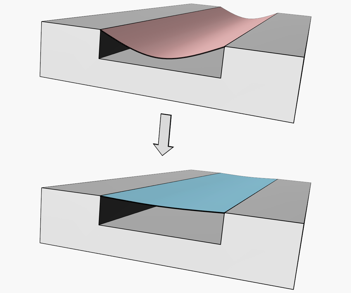
The embossing process is comprised of 4 steps and requires a specialized press that allows precise control of temperature and force:
- The soft embossing tool and plastic blank are heated to a material-optimized temperature.
- The soft embossing tool is pressed with controlled force into a plastic blank, creating the desired microfluidic geometry.
- Both the soft embossing tool and device are actively cooled. By continually applying force during cooling, shrinkage and warpage due to cooling are minimized.
- After the soft embossing tool and device have sufficiently cooled, they are separated, or de-molded. The plastic microfluidic device is now ready for post-processing.
Edge embossing offers post-processing services, including packaging and lidding of the final microfluidic device.

Figure 4 – Illustration of the embossing process.
Greater design flexibility and extended master lifetime
The process described above offers several advantages compared to techniques using rigid microfabricated mold inserts.
- The elastomeric nature of the secondary tool allows for the production of device geometries that would otherwise be problematic, including zero-draft angle, high aspect ratios, and undercut features.
- The original master mold is preserved in its original condition, used only once to create the secondary tool.
- The secondary tool can be used to create tens of thousands of final parts. The cost of generating a new secondary tool is significantly lower than making a new microfabricated master.
Plastic parts with less built-in stress
Another major advantage the soft embossing process is the low thermal stresses in the final manufactured parts.
In injection molding, there is a significant thermal gradient between the tool itself and the molten resin introduced into the cavity. This gradient, combined with the high-speed flow of the plastic, causes substantial internal stresses in the finished part. Such stresses can lead to warp, premature fatigue, and substantial nonuniformity of optical properties.
For hard embossed parts, although resin motion is reduced by eliminating the molten injection step, there is still a sharp temperature gradient between the tool and the plastic, and between the thermoformed and non-thermoformed portion of the finished part. This can result in significant stresses.
In soft embossed parts, the entire mold is heated and cooled at the same time as the plastic, and the resin is stationary inside the cavity. Since all the plastic (not just the surface) is heated and cooled to a uniform temperature during the cycle, all major sources of stress are eliminated.
Summary
There are many approaches to transitioning microfluidic design to a manufacturable plastic device. Compared to other techniques, soft embossing imposes fewer design constraints on the geometries of microfeatures, produces parts with less built-in stress, and requires a significantly lower investment for tool production and replacement.
References:
[1] Wu, C.H. & Kuo, H.C. J Mech Sci Technol (2007) 21: 1477
[2] Worgull, M., Heckele, M. & Schomburg, W.K. Microsyst Technol (2005) 12: 110
[3] Teh, S., Lin R., Hung L. & Lee A. Lab on a chip (2008) 8: 198

The Latest From Edge Precision

Considerations When Switching from PDMS to Thermoplastic Microfluidics

Sealing Methods for Embossed Microfluidic Devices
